What do street lamps, large motors, data centers, and stadiums have in common? They all require a reliable and substantial supply of electricity.
However, accessing electricity for a specific application is not as simple as connecting directly to the power lines. The high-voltage electricity in transmission lines is designed for long-distance transport and is too powerful for direct use in most equipment. To make it usable, electricity must pass through a transformer, which converts it to a suitable voltage level for end-use applications.
While many people recognize what a transformer looks like, understanding how it works can be less obvious. Whether you are planning to purchase a transformer or installing one, knowing its function and operation is essential for making informed decisions. This article provides an introduction to transformers, explains why they are necessary, describes how they work, and highlights their key components.
In simple terms, a transformer is an electrical device that changes an input voltage into a different output voltage. This voltage change can either step up (increase) or step down (decrease) the electrical power, depending on the needs of the application.

Electrical energy consists of two fundamental elements: current and voltage.
Current is the rate of flow of electrical energy, measured in amps.
Voltage is the force driving that electrical energy, measured in volts.
A useful analogy is to think of electricity like water flowing through a pipe:
Current is the rate of water flow.
Voltage is the water pressure.
To transport water from a city reservoir to homes, businesses, and factories, large pipes and high water pressure are required. Similarly, high-voltage electricity is necessary to transmit power efficiently over long distances.
Now imagine connecting a high-volume, high-pressure city water pipe directly to your kitchen sink. The faucet would burst, and water would flood your home. Just as pressure regulators reduce water pressure for safe household use, transformers reduce electrical voltage to levels that are safe and usable for different applications.
Electricity in power lines can exceed 300,000 volts—a tremendous amount of “electrical pressure.” Step-down transformers reduce this voltage to usable levels for homes, businesses, and industries.
These transformers range from:
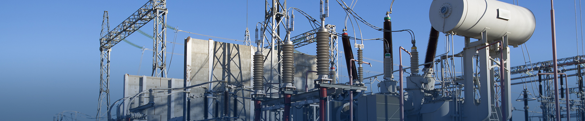
Massive substation transformers in utility yards,
Pad-mounted transformers outside businesses,
Pole-mounted transformers atop power poles.
Commercial and industrial operations typically use large three-phase transformers, providing voltages such as 480V or 208V. Homes and small businesses rely on smaller single-phase transformers delivering 120/240V. In this discussion, we will focus on three-phase distribution transformers, which are commonly used in industrial and commercial power distribution.
A transformer works according to the law of energy conservation, which states that energy cannot be created or destroyed, only transformed. Therefore, a transformer does not generate electricity; it only changes the voltage to suit the needs of the user.
Transformers achieve this voltage change through electromagnetic induction.
When an alternating current flows through a wire (conductor), it creates a moving magnetic field around the conductor. If a second conductor is placed within this changing magnetic field, the magnetic flux induces a current in the second conductor.
Voltage can be increased or decreased by wrapping the two conductors into coils with different numbers of turns. The coil with more loops is connected to the source, while the coil with fewer loops is the secondary. When the primary coil with more loops is energized, a current is induced in the secondary coil with fewer loops, producing a lower voltage than the primary coil.
This is the basic principle by which transformers step voltage up or down between circuits.
The first coiled conductor where electricity enters a transformer is called the primary coil, while the coil where the current is induced is called the secondary coil. Both the primary and secondary coils, also known as windings, are typically made of aluminum or copper and are wrapped around an iron core. The iron core strengthens and directs the changing magnetic field, improving induction efficiency. As the magnetic field fluctuates, the metal core slightly expands and contracts, which produces the humming or buzzing sound commonly associated with transformers.
Each loop of wire around the iron core is called a “turn.”
The voltage produced by a transformer depends on a simple rule: the ratio of turns between the primary and secondary coils determines the voltage ratio. For example, if the turns ratio is 25:1, the voltage is transformed at a ratio of 25:1. To achieve a specific voltage, the transformer is designed with the exact turns ratio required. A transformer with a 25:1 turns ratio, for instance, would step down 12,000 volts to 480 volts.
In three-phase transformers, the coils are connected in either a delta or a wye (star) configuration, depending on the system design and application requirements.
Transformers come in many configurations and types, such as unit substations, pole-mounted transformers, medium-voltage dry-type, and general-purpose low-voltage dry-type transformers. Despite different designs, they all share similar core components. Below is an overview of the parts found in oil-filled padmount transformers.
The core is made of thin, stacked sheets of steel. The transformer’s windings are wrapped around this core. When current flows through the windings, it induces a magnetic field. The core focuses this magnetic coupling, ensuring efficient energy transfer between the primary and secondary windings.
Coils are the windings, typically made of aluminum or copper, wrapped around the core. They consist of a primary winding, which receives voltage from the utility, and a secondary winding, which steps the voltage up or down depending on the application.
Bushings are insulated terminals that allow electricity to safely pass through the transformer tank wall without direct contact. They connect the transformer to the power source on the high-voltage side and to the load on the low-voltage side.
Transformer fuses protect the electrical system if a fault occurs within the transformer or downstream equipment. When exposed to excessive current or heat, a thin wire element inside the fuse melts, opening the circuit and disconnecting the transformer from the power grid.
Voltage adjustment taps allow operators to maintain the correct secondary voltage when the primary voltage varies. Adjusting the tap changer rotates it to disengage small sections of the primary winding, altering the primary-to-secondary turns ratio and adjusting the output voltage.
A load break switch (LBOR switch) is a rotary switch that enables workers to manually disconnect the transformer from the power grid, de-energizing the core and coils. These switches can operate even when the transformer is energized and “under load.”
Transformer fluid (oil) cools the transformer during operation. The oil circulates through ducts between the windings, serving as both an insulator and a cooling medium. Only liquid-filled transformers contain this fluid.
Gauges monitor operating conditions, including oil level, temperature, and tank pressure. Larger transformers may have more advanced monitoring systems.
A pressure release device vents excess pressure from the transformer tank, which can build up due to overheating or internal faults. This prevents the tank from reaching a critical pressure level that could cause rupture.
The nameplate is a metal or plastic placard providing essential specifications and operational details, such as kVA rating, voltage rating, phase, winding diagram, cooling class, and other important information.
The principle behind transformers is simple: they receive electricity at one voltage, change the voltage, and then redistribute electricity at the new voltage for use in a wide range of applications.
Electricity is essential in virtually every setting, from homes and businesses to industrial facilities. Transformers make it possible to bake pizzas, dry hair, melt snow on sports fields, and power data centers. They are a vital part of daily life and the backbone of modern electrical systems.
Whether you are new to transformers or have been working with them for years, this article aims to provide a clearer understanding of how transformers work, their key components, and their applications.
If you are planning a project that requires a transformer, contact us today for expert guidance and support.

Electrical Transformer Procurement Checklist: Sizing, Standards, Testing and Delivery
Electrical transformer procurement involves more than requesting several prices for the same kVA rating. A technically incomplete inquiry can produce offers that look comparable but include different insulation levels, losses, etc.
Jul. 30, 2026

How to Choose the Right Electrical Transformer for Your Project
Selecting an electrical transformer is not simply a matter of matching an incoming voltage to an outgoing voltage. The transformer must also support the real load profile, withstand expected fault conditions, operate within the site environment.
Jul. 30, 2026